|
Bulletin
|
| Preparation of Screened Cable for Installation of Primary Connectors |
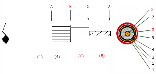
| The objective is to strip back the different layers to end up with the cable as shown in Figure 1, whereupon a 52Super connector may be applied. |
 |
| Figure 1 |
Figure 2 |
(1) Sheath / Jacket
(4) Metallic Screens
(6) Insulation
(8) Conductor |
(2) Armor
(3) Separator
(5) Insulation screen
(7) Conductor screen (optional)
|
|
|
Amerace offers the following suggestions (only) for cable preparation. The cable manufacturer may need to be consulted, since screened cables come in a large variety of constructions. Figure 2 illustrates the possible layers, and the number of possibilities is greatly increased by the use of different materials and constructions for the layers. Thus the following method cannot be definitive, but we have tried it on several different cables, and it works effectively.
Standard electrical tools such as knives, cutters and pliers can be (and are) used to successfully prepare screened cables for connectors, if done carefully. But to improve speed and especially to achieve consistently good results, more specialized tools can be useful.
The following suggestions are based on the use of an AMP 606700-1 tool which we have found satisfactory for the purpose. If you have suggestions for other tools or methods that you would like to share with other installers, we would be pleased to publish them if you contact us.
|
| 1. |
Set the tool and cut at point B down to the insulation, being careful not to nick the insulation. The sheath/screen/separator (if there is one) from point B to point D can generally be pulled off cleanly in one piece. |
| 2. |
The semicon layer (if there is one) from point B to point C must now be removed, or it may cause a flashover between the conductor and the screen. If an extruded semicon layer is used it sometimes can just be pulled off unless it is firmly bonded to the insulation. In the latter case, free this layer at point D with a knife, and then grab it with a pair of pliers (damaging the insulation at this point is not a concern since it will be removed in the next step), and pull and twist it back to point B, where it should come off cleanly, if the cutting in step 1 was done correctly. If the semicon is tape, this can generally be easily pulled back to point B and cut off with cutters. |
| 3. |
Strip the insulation from the wire from point C to point D. To do this reset the tool and cut at point C, after which the insulation (and conductor screen, if there is one) can generally be pulled off cleanly in one piece. |
| 4. |
Remove the sheath from point A to point B. To do this reset the tool, and cut at point A, after which the sheath can generally be pulled off cleanly in one piece, leaving a clean and neat bare screen. |
The cable is now ready to apply an Amerace® 52Super kit.
For a description of how to do this, click. |

Photo of a primary cable prepared in this way. |
|
Note: A review of the above instructions will show that the tool needs to be reset three times for each connection. For speedier installation it may be advisable to 'calibrate' the tool by determining the three settings, and marking them on the blade adjuster. Or three different tools could be used. |
| How Do I Size A Connector? |
| Three pieces of information are required to properly size a connector. |
| 1. |
Sheath OD (outside diameter) |
So that the rubber housing will provide an effective water and electrical seal between the sheath and the cable. |
| 2. |
Insulation OD |
So that the rubber housing will provide an effective electrical and water seal between the screen and the conductor. |
| 3. |
Conductor gage and construction (stranded or solid) |
So that the crimp barrels of the pins and sockets will properly accommodate the wire. |
| ..
AMP 606700-1 Cable Stripper
|
, |
| .. |
|
|
|
|
|
|
|